
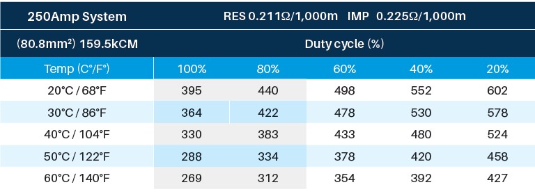
Temperature matters. One common oversight in runway electrification selection is failing to account for ambient temperature variations. According to NFPA 70 NEC Article 610, load calculations must consider the operating temperature along a 9m (~30ft) span. Ground-level temperatures are typically lower than those near the ceiling of a manufacturing or processing facility. Ignoring this difference can result in inaccurate calculations and potential system issues.
Duty cycle
Conductors provide power to equipment with a variety of load spectrum and duty cycles. Very few cranes will utilise a runway conductor branch over a 60% duty cycle. Even cranes used in refuse, magnet or bucket service only use the principal energy load (hoisting up) at most 50% of the time. Unless the current load of the “second largest motor or group of motors” approaches the running current of the main hoist, there is little chance the load remains above 40% of demand otherwise.
As with any other application, a close analysis of your actual configuration and environment will pay dividends in the end.
Power feed location and number
Consideration of the location of the power feed is critical and can result in a massive voltage drop problem. Contact the factory for proper feed point count and locations to avoid such problems. Since aluminium and steel systems have voltage drop losses 40–460% higher than copper and are very often ‘applied’ from a catalogue rather than engineered, losses are often overlooked.
Determining load
Calculation of motor loads can be found in NEC 610.14(E). Below are two examples of sizing the system to your crane loads:
- For a single crane operating on its own conductor system, use the nameplate full-load ampere rating of the largest motor or group of motors for any single crane function, plus 50% of the nameplate full-load ampere rating of the next largest motor or group of motors.
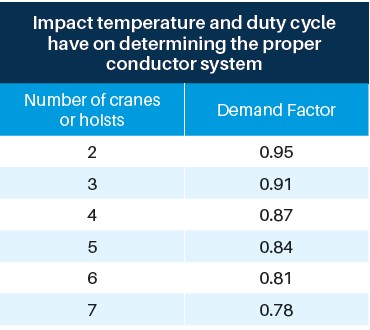
- For multiple cranes operating on the same conductor system, use the same method for a single crane for each crane. Add the results and multiply by the appropriate demand factor from Table 610.14(E) to determine the load (L).
Summary
It is critical to incorporate ‘load’, ‘operating ambient temperature’ at the crane elevation and ‘duty cycle’ when calculating the correct conductors for each application. Examples of key indicators of an undersized runway electrification system failure include burn spots on the conductor, melted or heat deformed splice covers, coil failures, buzzing or chattering relays and contactors, hot brake coils, for example.


